Indirect Solar Dryer
Development of a novel and economical Indirect Solar Dryer for food preservation using solar energy and automatic Arduino-based temperature and airflow controls.
Objective
Design and fabricate a low-cost indirect solar dryer that uses renewable solar energy to reduce the moisture content of agricultural produce, extending shelf life while preserving nutritional value — without any direct exposure of food to sunlight.
Key Outcomes
- Achieved automated temperature regulation using Arduino + DHT11 sensor
- Designed full 3D assembly in SolidWorks prior to fabrication
- Built and tested a working prototype using arc-welded steel framework
- Applied zeolite desiccant bed for enhanced moisture absorption
- Validated system with controlled drying trials on bananas and potatoes
Institution
Dr. A.P.J. Abdul Kalam Technical University
Role
Student Researcher
Duration
2022 – 2023
Project Members
H. Karan
Manikya
Shantanu Nautiyal
Project Mentor
Prof. Ashutosh Kumar
Dr. Sanjeev Kumar
Methodology & Design
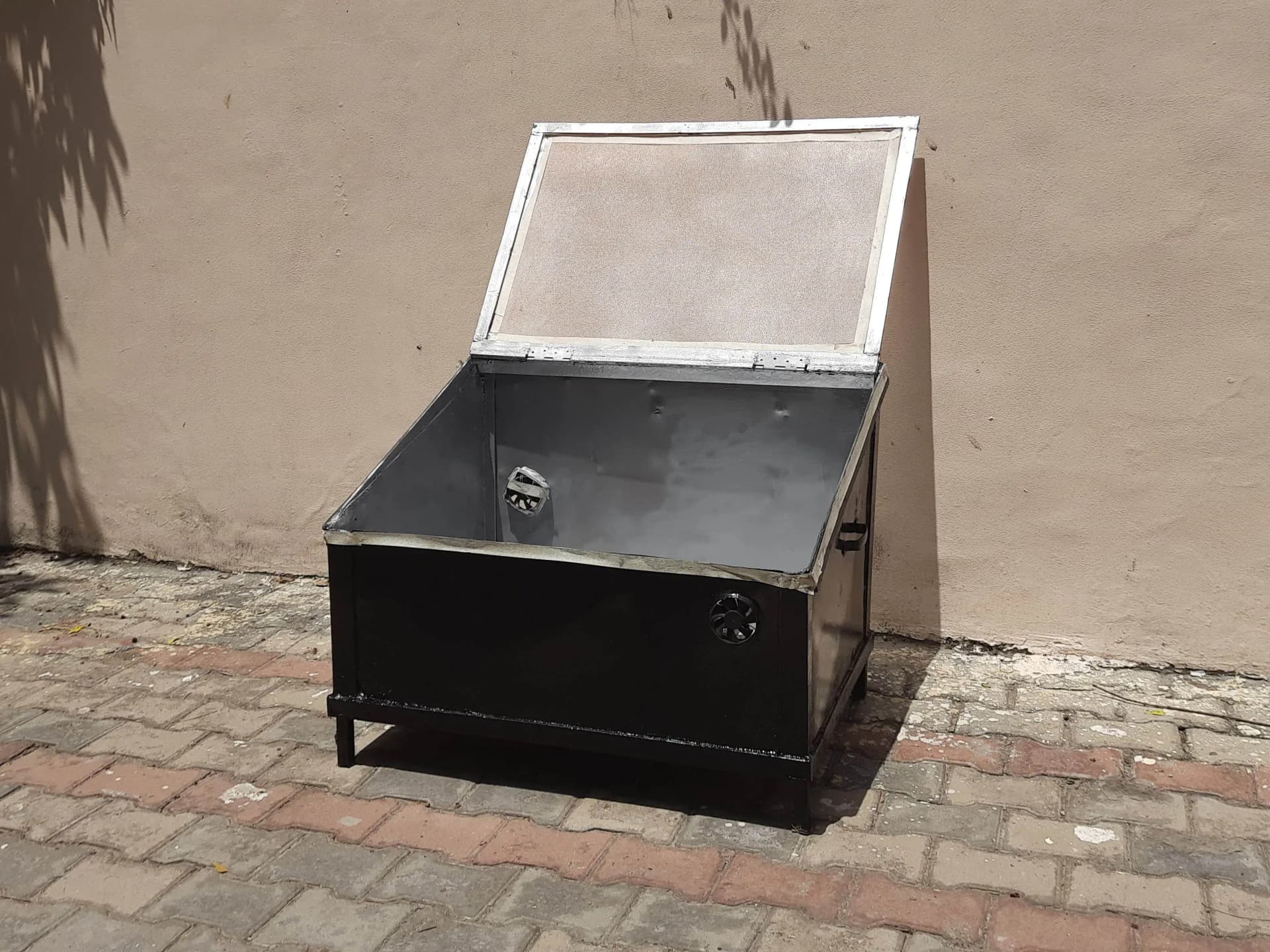
The system was designed around indirect heating principles — solar energy heats air in a dedicated collector channel, which is then circulated through the drying chamber to dehydrate produce without direct sun exposure.
Problem Statement
The objective of this study is the development of a novel and economical Indirect Solar Dryer for Food Preservation. The system aims to improve the shelf life and quality of dried foods such as bananas, potatoes, etc., by effectively reducing their moisture content.
System Design
Exhaust Air Flow
The exhaust fan is placed at the back of the drying chamber to release additional air and excess heat efficiently.
Cold Airflow
The inlet fan is placed at the front to intake fresh ambient air while maintaining the desired inner chamber temperature.
Conventional Trays
Custom wooden trays were integrated to hold and arrange agricultural products neatly during the drying process, optimizing air distribution.
Air Circulation & Sensors
Selected fans capable of providing the ideal airflow rates for efficient drying, paired with a DHT11 temperature and humidity sensor to continuously monitor the drying environment.
Arduino Microcontroller Integration
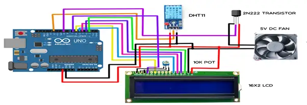
- Connected the DHT11 sensor to measure and monitor temperature and humidity levels inside the dryer.
- Connected the motor driver to control the air circulation fan, adjusting the fan speed dynamically based on desired drying conditions.
- Integrated an I2C module with the display to reduce overall wiring complexity and ensure reliable readings in real-time.
Hardware Requirements
All components were selected to balance cost-effectiveness, durability under high-temperature conditions, and compatibility with the Arduino control system.
- Sealed box built to precise dimensions
- Polycarbonate top sheet cover
- Air circulation fans (exhaust and intake)
- Zeolite Bed (drying medium)
- Arduino Uno Microcontroller board
- L298N Motor Driver
- DHT11 Temperature & Humidity Sensor
- 16x2 LCD Display with I2C Module
- 12V DC Adapter & connection wires
Arduino & Programming
The Arduino Uno acts as the embedded controller — reading sensor data, computing dynamic PWM signals to regulate fan speed, and displaying live temperature and humidity readings on the LCD.
Wiring and Pin Configuration
- DHT11 Sensor: Data pin → Arduino Digital Pin 12.
- L298N Motor Driver: IN1–IN4 → Digital Pins 2–5. ENA/ENB → Pins 9 and 10.
- I2C Display Module: SDA → Analog Pin A4, SCL → Analog Pin A5.
Programming Steps
1. Read & Verify
Collect raw readings from the DHT11 sensor and display them on the 16x2 LCD screen.
2. Dynamic Logic
Process temperature readings and compute PWM to step up or down fan speed.
3. System Safety
Add thresholds to prevent overheating, shutting off fans if the environment stabilizes.
4. Serial Monitoring
Relay metrics back to compile and trace logs, fine-tuning variables for different crop configurations.
Design Consideration
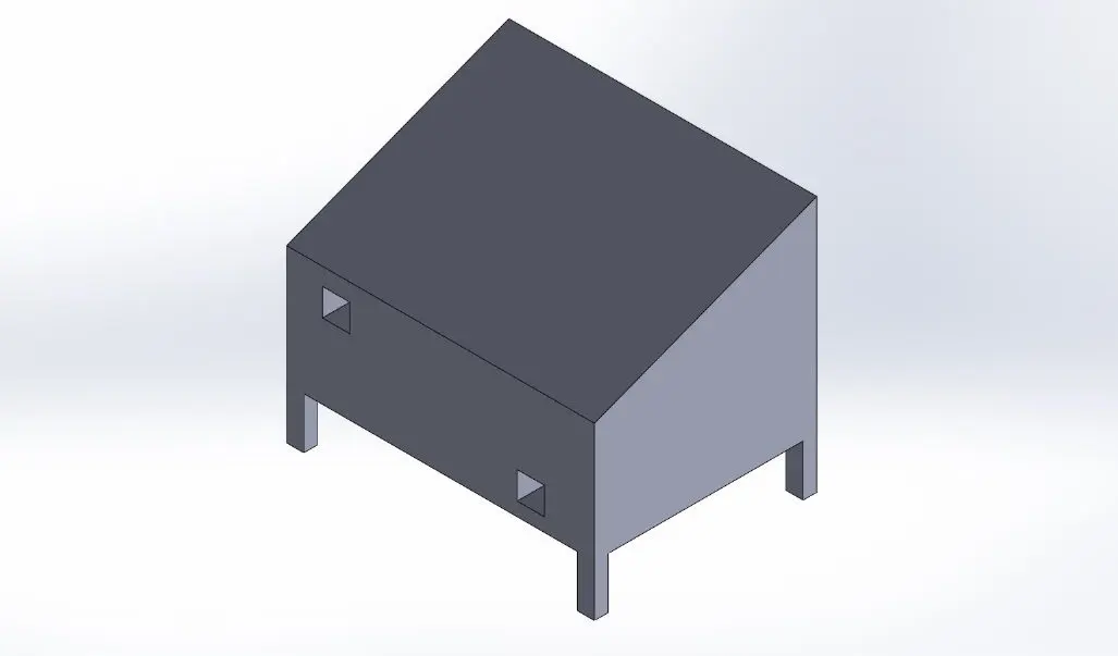
SolidWorks was used to design, simulate, and validate every component before fabrication — ensuring structural integrity, optimal airflow paths, and correct dimensional tolerances.
Key CAD Focus Areas
- 3D Modelling & Assembly: High fidelity modelling of the zeolite bed chamber, collector body, polycarbonate sheets, and fans.
- Thermal & Airflow Simulation: Simulated thermal behavior to locate heat traps and maximise convection currents.
Structural Integrity
- Insulation Design: Insulated walls to prevent energy loss and maintain a stable drying environment.
- Polycarbonate Angle: Slanted design optimised to capture maximum solar radiation during peak hours.
Construction Phases
The dryer was fabricated in six sequential phases — from framework cutting and arc welding through to surface coating and final electronics integration.
Angle Cutting & Framework Preparation
MS angle sections were measured and marked according to the SolidWorks drawing dimensions. An angle grinder with a cutting disc was used to achieve precise cuts. Accurate cutting at this stage was critical — dimensional errors here would propagate through all subsequent assembly steps and compromise the structural squareness of the final enclosure.
Arc Welding Assembly
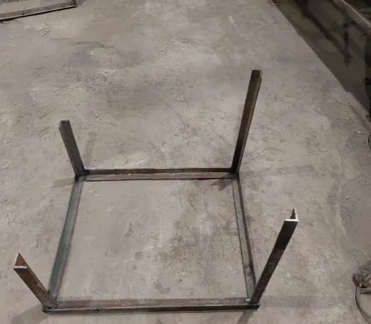
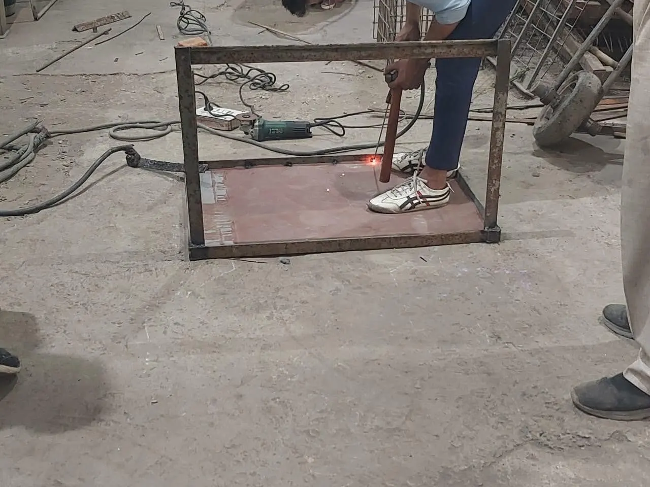
The cut angle sections were joined using shielded metal arc welding (SMAW). Tack welds were first applied to hold the pieces square before full seam welding. Welding parameters were carefully controlled to avoid heat distortion of the frame. The resulting joints provide a rigid, load-bearing skeleton capable of withstanding long-term thermal cycling during operation.
Boundary Structure Formation
With all angle sections welded, the complete boundary frame took shape — a rectangular cage defining the outer perimeter of the dryer. This structure acts as the primary load-bearing skeleton, providing mounting points for the steel sheet panels, polycarbonate top cover, electronic components, and internal wooden drying trays. Diagonals were checked for squareness before proceeding.
Steel Sheet Cutting & Enclosure Welding
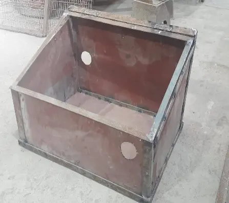
Mild steel sheets were cut to exact panel dimensions using a jigsaw and angle grinder, then welded flush onto the inner faces of the boundary frame. These panels form the four side walls and the base of the drying chamber — creating an airtight enclosure that channels heated air through the system. Seam welds were ground smooth to ensure proper paint adhesion in later phases.
Body Priming
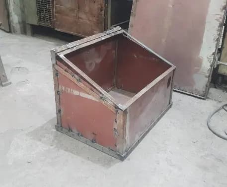
All metal surfaces — both interior and exterior — were cleaned with a wire brush to remove weld spatter and mill scale, then wiped down with a degreaser. A uniform coat of zinc phosphate primer was applied to inhibit rust formation and create a chemically bonded base for the topcoat. Priming is especially critical for an outdoor solar application where the enclosure is continuously exposed to heat, UV radiation, and moisture.
Applying Solar-Absorptive Coatings
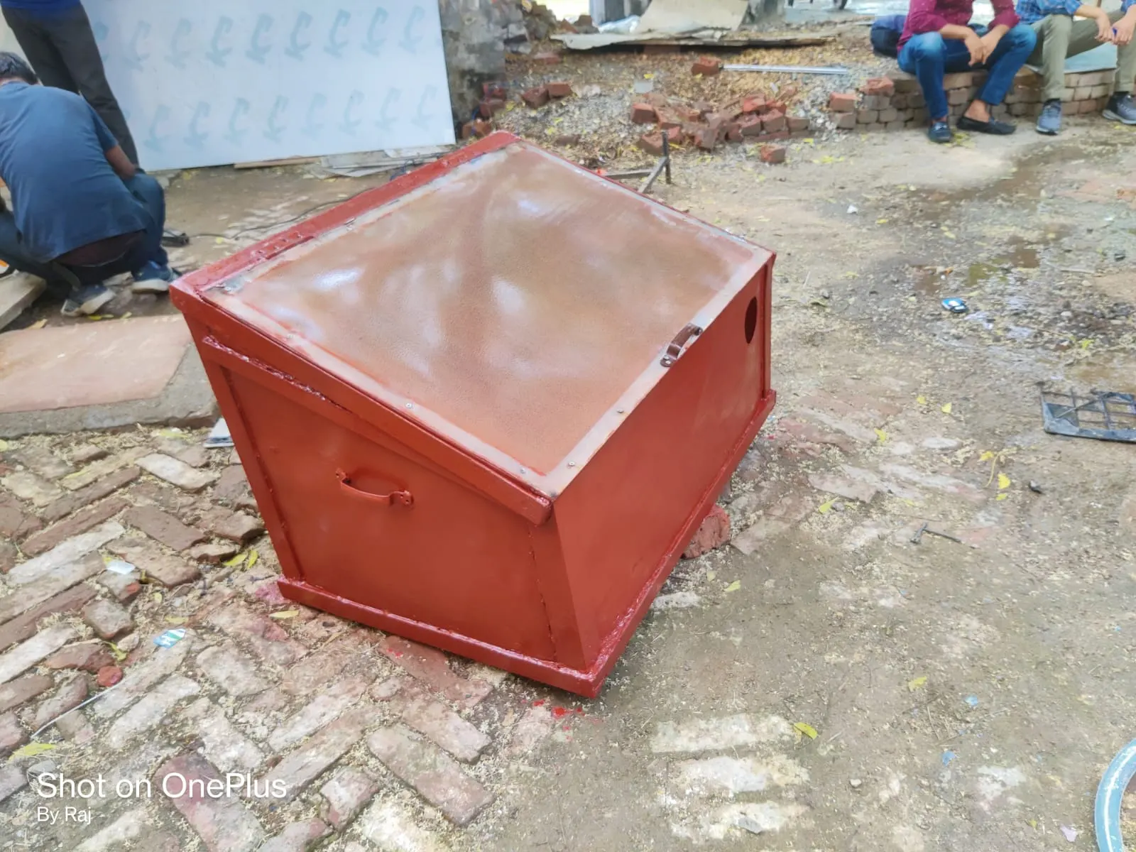
The exterior body was finished in matte black paint to maximise solar radiation absorption — a black body surface achieves near-unity absorptivity across the solar spectrum. The interior chamber walls were painted grey to diffuse and distribute absorbed thermal energy evenly across the drying trays, avoiding localised hot spots that could unevenly dry or scorch produce.
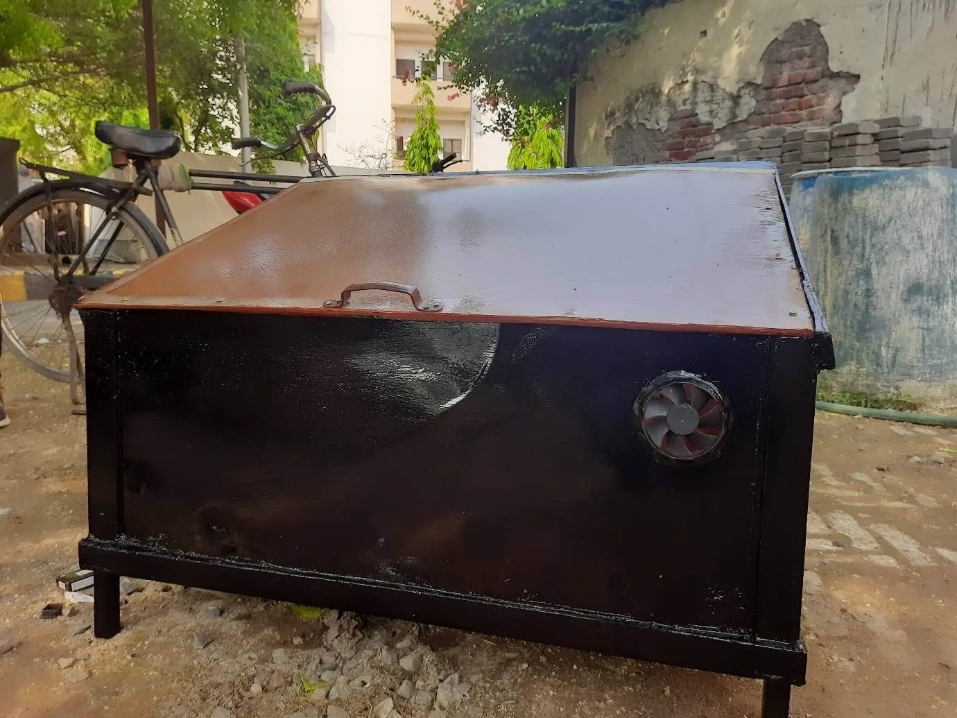
Finishing & Component Integration
Once painting was complete, self-groove screws were used to securely fasten the polycarbonate sheet to the top frame. Hot glue was utilised to mount the Arduino microcontrollers, drivers, and displays within insulated cavities, protecting the electronics from the heat of the main drying chamber before all jumper wire paths were routed and tested.